
MOPAR A833 4-SPEED TRANSMISSION & COMPONENT SPECIALISTS
Before You Order
To ensure the quickest service and correct parts, please read carefully through the descriptions below.
TRANSMISSION REBUILD KITS, SYNCHRONIZERS, AND INTERNAL PARTS
Due to numerous internal variations in the A833 4-speed transmission throughout its 23 years of production, identification of certain components is critical in determining the correct rebuild kit, synchronizer stop rings, bearings, etc.
Casting numbers obtained from the:
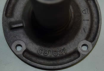
Front Input Bearing Retainer
(the sleeve bolted to front of the transmission that the throw-out bearing rides on)
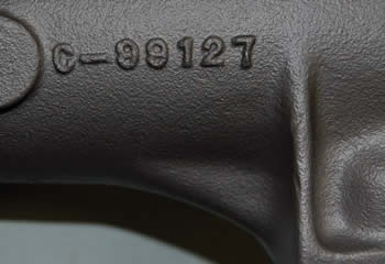
Extension Housing (Tailshaft)
will enable us to verify the correct bearings, tailshaft bushing, and seals for your transmission. Casting numbers from the main case DO NOT supply any useful information, as the same cases were machined for both large and small front bearings.
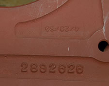
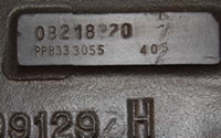 Beginning with the 1968 model year (July 1, 1967), the main case has a small (3" by 7/8") raised, machined rectangular pad on the passenger side of the transmission, just above the casting number. Along with the vehicle's serial number stamped onto it, this pad will have a second line beginning with "PP833" followed by a 4-digit (10,000 day calendar) date code, such as "2264" (10-9-67) or "3055" (12-08-69) and sequential assembly number (405) for that day (pictured). This date code is helpful to us
 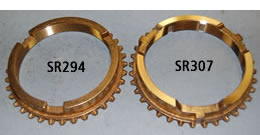 in determining what synchronizer stop ring is used, as MOST 1970 and later (2895, 7-1-69) transmissions use the lug-style (SR307) synchronizer stop ring. All 1969 and earlier transmissions (Up to 2894, 6-30-69) used the 3-notch style (SR294) synchronizer stop ring, UNLESS the transmission had been serviced in the early 1970s, and the new style synchronizer assemblies were installed.
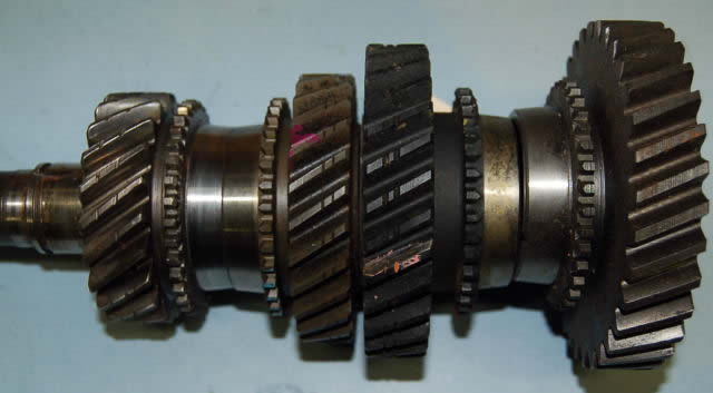
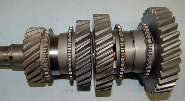
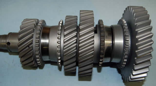
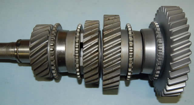
As mentioned in the History of the A833 Transmission, many different gear ratios have been used in the Chrysler 4-speed transmission in 23 years. Tooth count on gears help in identification, BUT some gears have the same tooth count even though they are from a different ratio.
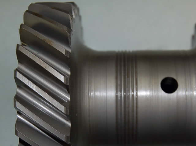
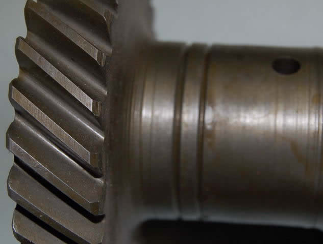
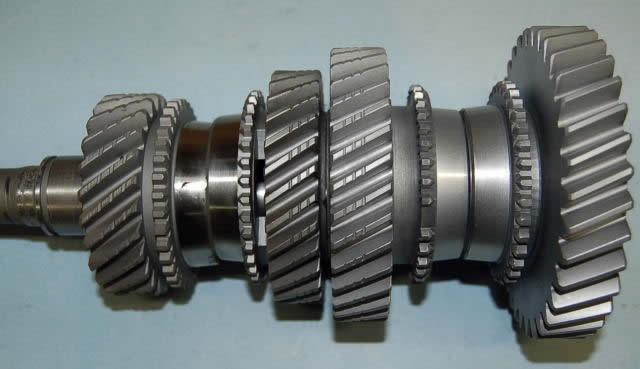
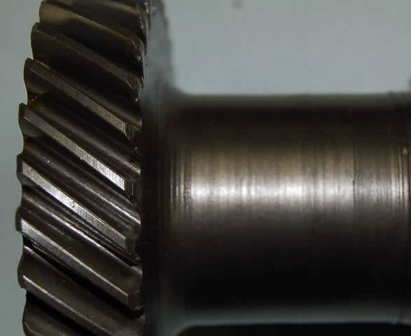
One example is the second speed gear from the 2.66- and 2.47-ratio, 23-spline transmissions. Although both have 34 teeth, they are NOT interchangeable. Identification marks (1) on the tips of the 2nd and 3rd speed gear teeth/main drive pinion teeth and (2) between the cluster pinion drive gear/third gear were used to distinguish the different ratios as follows (click photos below to enlarge):
18-Spline Transmission
Cluster 6 Grooves
Speed Gears 2 Grooves
18-Spline Transmission
Cluster 2 Grooves
Speed Gears No Grooves
23-Spline Transmission
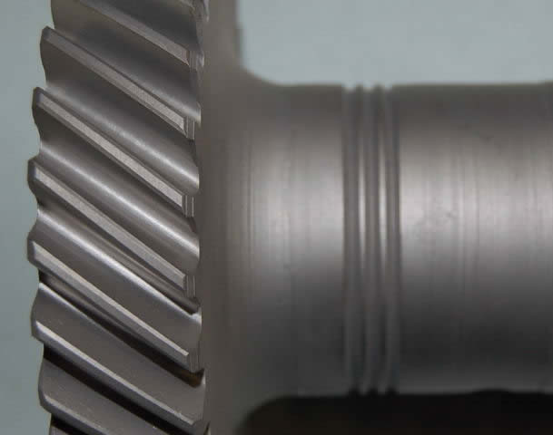
Cluster 3 Grooves
Speed Gears 3 Grooves
23-Spline Transmission
Cluster No Groove
Speed Gears No Groove
23-Spline Transmission
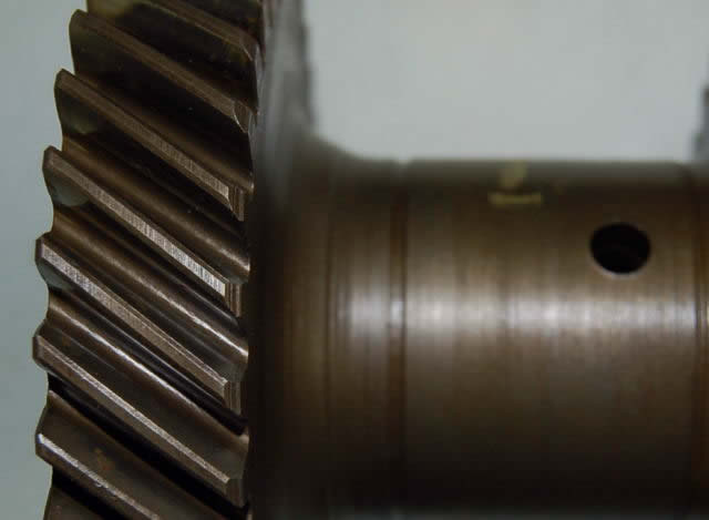
Cluster One Groove
Speed Gears One Groove
First speed gears carry no identification marks, as the three different 23-spline transmissions utilized the same 1st gear. The two 18-spline ratios also used the same first gear. However, NO gears are interchangeable between 18- and 23-spline transmissions.
This might be a good time to mention that all 18-spline 1st, 2nd, and 3rd-speed gears are bronze bushed. However, not all bushed gears are 18-spline. We have seen some early NASCAR 23-spline transmissions with bushed speed gears as well.
 With all this said, please have available the following information before ordering transmission rebuild kits, synchronizer rings, or other internal parts:
- Casting number of front bearing retainer
- Casting number of tailshaft housing
- Style of synchronizer rings (early notch style SR294 or late lug style SR307)
- Gear ratio/tooth count of needed gears
- Date code of transmission
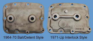
- Ball/detent (1964-70) or interlock (1971-up) style side cover
CLUTCH AND CLUTCH LINKAGE PARTS
 As in the case of transmission variations, many different flywheels, clutches, bellhousings, clutch forks, clutch linkage geometry, etc. were used in Chrysler Corporation vehicles during the same period. To ensure you get the correct clutch related parts, please have the following information available at time of ordering:
- Bellhousing casting number (this is found on rear surface of bellhousing where the transmission bolts up)
- Tooth count of flywheel ring gear (generally 130, 143 or 172 teeth)
- Overall length of clutch fork
- Transmission input spline count and casting number of front bearing retainer
SHIFTER MECHANISM IDENTIFICATION
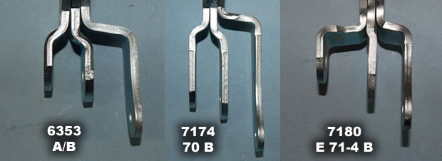
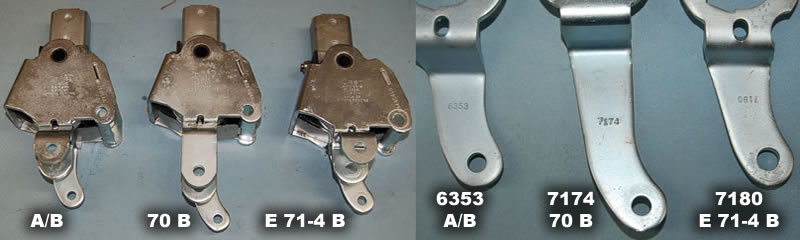
All factory (original equipment) Mopar/Hurst 4-speed shifter mechanisms can be identified by the four digit number on the reverse lever, which is the longest of the three. 1968-75 A-body and 1968-69 B-body uses #6353 (as does the later truck overdrive), 1970 B-body #7174, and 1970-74 E-body/1971-74 B-body #7180 (which happens to be stamped upside down). All of these have 5/16" holes for the reverse linkage rod attachment. A common Hurst aftermarket/replacement shifter mechanism (for most A & B applications) has #6370 on the reverse lever, and utilizes a 1/2" hole and a reducer bushing.
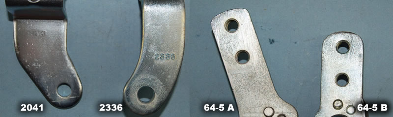
The 1963 T10 Borg Warner Hurst mechanism reverse lever is #2041, and the early 1964-65 A & B-body Hurst mechanisms both use #2336 reverse levers, which is stamped on the right side instead of the left. However, the shift handle stubs (where the Hurst handle bolts on) is different on these two mechanisms.
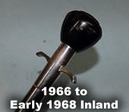 1966 through about January 1968 production, Ma Mopar used an Inland shifter mechanism and shift handles, which are easily identified by the reverse lockout "T" handle, and the unique teardrop shaped shifter knob.
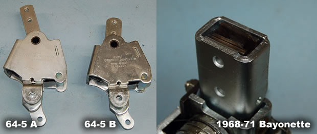
Two different shift handle attachments have been used on the Hurst mechanisms. The early mechanisms (1963 T10/1964-65) use a solid shift stub that is drilled and tapped for attachment bolts. 1968 introduced the slip-in (or bayonet style) handle attachment, and was used until some early 1971 applications. To remove these handles from the mechanism, a 010" feeler gauge is inserted between the handle and the stainless steel retainer on the drivers side, which releases the locking tang from the notch in the handle, allowing the handle to be pulled out.
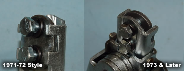
In late 1970, some applications switched to the bolt-on style handle attachment. The first style is similar to the early bolt-on mechanisms, as the threaded anchor is on the stick bottom, and the bolts pass through a small plate to clamp the shift handle into the mechanism. On later bolt-on style mechanisms, the holes are in the stick bottom, and the small plate has the threaded anchors.
Spacing and length of the three levers are unique to each style mechanism.